A one-year retrospective of my first research project
September 15, 2022
I just added a page on my research to this website!
In accordance with this theme, I just wrote a little bit about my first project in the Quantum Circuits Group -- keep reading!
Overview
I designed a voltage divider and low-pass filter circuit which delivers constant current to a magnetic coil while also dissipating any noise. I was simultaneously taking the circuit theory course, so it was a great learning experience to actually be modeling/simulating/building my own (more complicated) RC filter while we were learning about (less complicated) RC filters in class.
Design space exploration
The first part of the project involved taking an RC filter template and tuning the parameters to construct a circuit meeting our design criteria. The goal was to maintain a high enough ratio between two resistances (voltage divider between R1 and R2 determines the current to the load) while keeping a low-enough cutoff frequency (low-pass filter).
I modeled the coil as a 1 ohm resistor and then varied the other resistances, using LTSpice to calculate the cutoff frequency for each set of parameters. Part of the challenge was that I had to stick to practical resistances and capacitances -- for example, setting R2 as low as possible would have been useful for increasing the resistive ratio and decreasing the cutoff frequency, but we had to set a minimum value to ensure that its power dissipation would not overwhelm the cryogenic refrigerator.
Initially, I was manually searching for sets of resistance values that produced the correct DC current and then manually determining the cutoff frequency by looking at plots within LTSpice. This was taking a long time. So I wrote a program for my TI-Nspire which took R1 and R2 as inputs, automatically solved for the remaining resistances, and then returned the cutoff frequency. This sped up the process, and I quickly generated enough data points to find the optimal resistive ratio (R1/R2) and its corresponding cutoff frequency.
(Recently, I was discussing the project with my PhD student mentor, and we both realized that the whole thing probably could have been done with a couple button presses in AWR. Oh well.)
PCB design
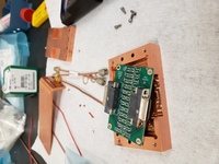
I put twelve copies of this two-port network onto a PCB schematic and designed my first-ever circuit board. The goal here was to have twelve independent lines, each with two input pins and two output pins (for a total of 24 inputs and 24 outputs). So I added two 25-pin D-Sub Micro-D connector to the board, one for input and one for output.
(While designing the PCB in KiCAD, I was routinely working with lengths on the scale of 1mm, but I didn't really have an intuition for how small that was. So when I finally saw the finished board in physical form, I was especially surprised by the size of my 0805 components which had seemed so reasonably-sized on KiCAD's 0.1mm grid.)
Metal mounting hardware
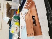
Finally, I designed some metal (OFHC) mounting hardware for the PCB so that it could be installed onto the 4K plate of our dilution refrigerator! I learned how to use Autodesk Fusion 360, which was very different from the Tinkercad software I had been using for 3D printing.
Conclusion
This was an enjoyable and educational first project!
On the electrical engineering side, I learned a lot about the PCB design process, including how to find the optimal parameters for a circuit given design criteria and physical constraints, how to convert the schematic into a PCB, how to find and order components for the PCB, and how to design auxiliary hardware for the PCB.
Prior to this project I had very little knowledge of what experimental research entailed. So this project was an effective introduction to research for me because it gave me an idea of the work involved in building equipment for an experimental setup.
I started going to the lab last semester, and I finally saw my PCB mounted into the fridge. It felt great to see the board I designed as part of a much bigger setup, and it was nice to hear that the board was working as expected.
Pictures


